
OSPF Basic Concepts - Part 1
Jul 09, 2019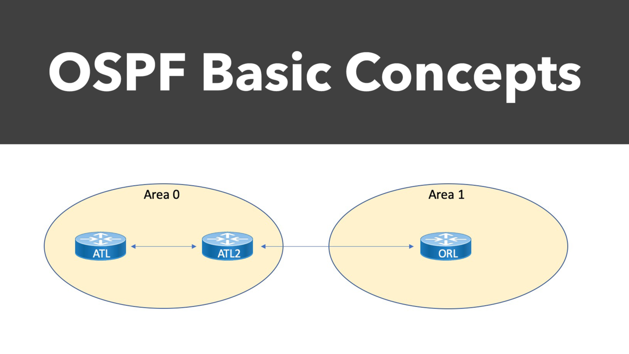
The OpenShortest Path First (OSPF) dynamic routing protocol is one of the most beloved inventions in all of networking, widely adopted as the Interior Gateway Protocol (IGP) of choice for many networks. In this blog series, you'll be introduced first to the basic concepts of OSPF and learn about its various message types and neighbor formation.
An Overview of OSPF
Where does the interesting name come from when it comes to OSPF? It is from the fact that it uses Dijkstra's algorithm, also known as the shortest path first (SPF) algorithm. OSPF was developed so that the shortest path through a network was calculated based on the cost of the route. This cost value is derived from bandwidth values in the path. Therefore, OSPF undertakes route cost calculation on the basis of link-cost parameters, which you can control by manipulating the cost calculation formula.
As a link state routing protocol, OSPF maintains a link state database. This is a form of a network topology map. Every OSPF router on the network implements this link state database and the map to networkdestinations. Included in this link state database for each prefix is the OSPF cost value. Remember, the OSPF algorithm allows every router to calculate the cost of the routes to any given reachable destination.
A router interface running OSPF will advertise its link cost to its OSPF neighbors. This prefix and cost information is cascaded through the network as OSPF routers advertise the information they receive from one OSPF neighbor to all other OSPF neighbor routers. This process of flooding link state information through the OSPF network is known as synchronization. Based on this information, all routers with OSPF implementation continuously update their link state databases with information about the network topology and adjust their routing tables.
We like to refer to OSPF as a hierarchical routing protocol. This is because an OSPF network can be subdivided into routing areas to simplify administration and optimize traffic and resource utilization. We identify areas by 32-bit numbers. We can express these as in decimal or in the same dotted decimal notation used for IPv4 addresses.
By definition, Area 0 (or 0.0.0.0) represents the core or backbone area of an OSPF network. Any other areas you might create (Area 10, Area 20, etc) must be connected to the backbone Area 0. If your areas are not connected as described, you must engage in a workaround procedure such as a Virtual Link (described later in this blog series). You maintain connections between your areas with an OSPF router known as an area border router (ABR). An ABR maintains separate link-state databases for each area it serves and maintains summarized routes for all areas in the network.
Neighbor and Adjacency Formation
Because OSPF is a complex routing protocol (unlike a much simpler protocol such as RIP), it uses different neighbor states in its operation. You should know and understand these different states not just for the academic exercise of possessing this knowledge. These states can become critical in your OSPF support and troubleshooting efforts. For example, you might have a router “stuck” in one of these states, and that information can prove critical in fixing the problem.
Here are the states and information you should know about each of them:
Down - This is the first (or initial) OSPF neighbor state. It means that no information (hellos) have been received from a neighbor, but hello packets can still be sent.
During the fully adjacent neighbor state (the Full state), if a router doesn't receive a hellopacket from a neighbor within the RouterDeadInterval time or if the manually configured neighbor is being removed from the configuration, then the neighbor state changes from Full to Down. Remember, the RouterDeadInterval time is 4 times the HelloInterval by default for OSPF.
Attempt - This state is only valid for manually configured neighbors in a Non-BroadcastMultiaccess (NBMA) environment. In this state, the router sends unicast hello packets every poll interval to the neighbor from which hellos have not been received within the dead interval.
Init - This state specifies that the router has received a hello packet from its neighbor, but the receiving router's ID was not included in the hello packet. When a router receives a hello packet from a neighbor, it should list the sender's router ID in its hello packet as an acknowledgment that it received a valid hello packet.
2-Way - This state designates that bi-directional communication has been established between two routers. Bi-directional means that each router has seen the other's hello packet.
This state is attained when the router receiving the hello packet sees its own Router ID within the received hello packet's neighbor field. In this state, a router decides whether to become adjacent to this neighbor. On broadcast media and non-broadcast multiaccess networks, a router becomes full only with the designated router (DR) and the backup designated router (BDR); it stays in the 2-way state with all other neighbors. On Point-to-Point and Point-to-Multipoint networks, a router becomes fully adjacent with all connected routers.
NOTE: At the end of this state, the DR and BDR for broadcast and non-broadcast multi-access networks are elected.
Exstart - Once the DR and BDR are elected, the actual process of exchanging link state information can start between the routers and their DR and BDR.
Exchange - In the exchange state, OSPF routers exchange database descriptor (DBD) packets. Database descriptors contain link-state advertisement (LSA) headers only and describe the contents of the entire link-state database. Routers also send link-state request packets and link-state update packets (which contain the entire LSA) in this state. The contents of the DBD received are compared to the information contained in the routers link-state database to check if new or more current link-state information is available with the neighbor.
Loading - In this state, the actual exchange of link state information occurs. Based on the information provided by the DBDs, routers send link-state request packets. The neighbor then provides the requested link-state information in link-state update packets. During the adjacency, if a router receives an outdated or missing LSA, it requests that LSA by sending a link-state request packet. All link-state update packets are acknowledged.
Full - In this state, routers are fully adjacent with each other. All the router and network LSAs are exchanged and the routers' databases are fully synchronized.
Remember that the full state is the normal state for an OSPF router. If a router is stuck in another state, it is an indication that there are problems in forming adjacencies.
While a much more complex IGP than something like RIP, surprisingly, the configuration is quite simple. In fact, there are currently two options for its configuration at the command line. You can configure OSPF using a network statement under the routing process (much like other routing protocols), or you can configure the interfaces to run OSPF in interface configuration mode. Examples 1 and 2 demonstrate the two configuration approaches using the topology shown in Figure 1.
Figure 1: A Sample OSPF Topology

Example 1: Configuring OSPF Using Network Statements

Notice in these configurations that we identify the local OSPF process on the router using a locally significant process ID value. In the example, the process ID of 1 is chosen for all the routers. Also notice that the network statement must contain a wildcard mask that indicates the significant bits in the network value that proceeds it in the command. On the ATL2 Area Border Router, a 32-bit wildcard mask of 0.0.0.0 is used to place one interface in Area 0 and another in Area 1.
Example 2: Configuring OSPF Using Interface-Level Commands

Example 3: Verifying OSPF

Notice the power of the show ip ospf neighbor command in order to verify the neighbor relationships and their state. On ORL, we examine the routing table to ensure we are learning the OSPF Inter Area route of 10.12.12.0/24.
That's going to wrap up Part #1 of our OSPF series. Coming up in Part #2, we'll take a look at the Designated Router and Backup Designated Router election process. Take good care.
