What is a "Leaf-and-Spine" Data Center Topology
May 09, 2017
For decades, we’ve heard about Cisco’s three-tier network design where we had the following layers: (1) Access, (2) Distribution, and (3) Core. The Access Layer connected to our end devices (e.g. clients and servers). The Distribution Layer redundantly interconnected Access Layer switches, and provided redundant connections to the campus backbone (i.e. the Core Layer). The Core Layer then provided very fast transport between Distribution Layer switches.

However, within today’s data centers, a new topological design has taken over. It’s called a Leaf-and-Spine topology, and in this short blog post, you’re going to learn the basics of how it’s structured.
Imagine a cabinet in a data center, filled with servers. Frequently, there will be a couple of switches at the top of each rack, and, for redundancy, each server in the rack has a connection to both of those switches. You might have heard the term top-of-rack (ToR) used to refer to these types of switches, because they physically reside in the top of a rack.
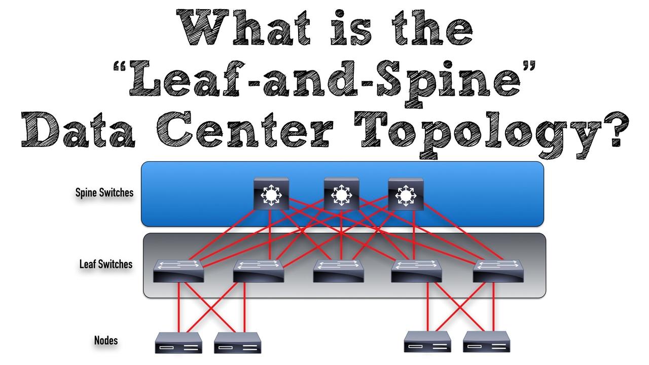
These ToR switches act as the leaves in a Leaf-and-Spine topology. Ports in a leaf switch have one of two responsibilities: (1) connecting to a node (e.g. a server in the rack, a firewall, a load-balancing appliance, or a router leaving the data center) or (2) connecting to a spine switch.

You’ll notice in the topology that each leaf switch connects to every spine switch. As a result, there’s no need for interconnections between spine switches. Also, unlike a leaf switch, all ports on a spine switch have a single purpose in life, to connect to a leaf switch. It’s also interesting to note that the uplink connections from the leaf switches to the spine switches could be either Layer 2 (i.e. switched) connections or Layer 3 (i.e. routed) connections.
Obviously, the types and number of connections between the leaf and spine switches vary with the switch models being used. However, as an example, let’s say that we had a leaf switch with 160 Gbps of bandwidth it could use to connect to spine switches. Depending on the type of GBICs (Gigabit Interface Converters) you’re using in your switches, you might have (as a couple of examples) four 40 Gbps uplinks from a single leaf switch to four spine switches (for a total of 160 Gbps), or you might have sixteen 10 Gbps uplinks (again, for a total of 160 Gbps).
By interconnecting your ToR data center switches in a leaf-and-spine topology, all of your switches are the same distance away from one another (i.e. a single switch hop). Another huge benefit is that through Cisco’s ACI (Application Centric Infrastructure) solution, you could administer all of the leaf and spine switches as if they all made up a single logical switch. In this logical switch, you could think of the spine switches as acting like the logical switch’s backplane, with end devices (e.g. servers, firewalls, load-balancers, or routers) connecting only into the leaf switches.

On that note, we'll wrap up this quick look at the leaf-and-spine topology.
Kevin Wallace, CCIEx2 (R/S and Collaboration) #7945


