
Fundamentals of VRF-Lite
Feb 24, 2016
Have you ever used some sort of virtualization software (e.g. vmware) to get multiple virtualized servers running on a single physical server? It’s a great way to save resources, by eliminating the need for extra physical servers. Well, similar to how we can virtualize multiple servers on a single physical server, we can virtualize multiple routers on a single physical router.
Each of these virtual routers can have their own independent IP routing table and are logically isolated from the other virtual routers residing in the same physical router. This can offer a solution to service providers wanting to keep their customers’ network traffic (including the IP routing tables of customers’ routers) isolated from one another. Or, in a large enterprise, perhaps you have a design requirement to segregate different applications (e.g. voice, video, and data).
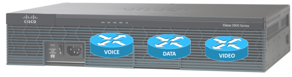
One solution Cisco offers to make this router virtualization possible is called VRF-Lite. Some literature from Cisco defines VRF as VPN Routing/Forwarding, because it’s commonly used in VPN environments. Other literature from Cisco defines VRF as Virtual Routing and Forwarding, which is the definition I typically use. By the way, each virtualized router is referred to as a VRF. So, a single physical router could be hosting multiple VRFs.
While it’s great that a single physical router can be running multiple virtual router instances, the question arises, “How does the physical router keep traffic from the virtualized routers separate when sending data to a neighboring switch or router?” The solution is actually quite simple, and similar to the old router-on-a-stick approach of having a router interface configured as an IEEE 802.1Q trunk interface, with a different subinterface for each VLAN, and each VLAN carries traffic for one VRF. Also, although it’s beyond the scope of this introductory blog post, please be aware that VRF-Lite can be configured to “leak” one ore more routes between router instances.
To demonstrate a basic VRF-Lite configuration, first consider the topology shown below. VRF-Lite is configured on the COMMON router. The Fa 0/0 interface on the COMMON router has three subinterfaces, one to carry traffic for each of the three VRFs. The VRFs are named: VOICE, DATA, and VIDEO.

Traffic from these three VRFs flows over a dot1Q trunk to switch SW1, which then sends traffic out to the appropriate destination router based on VLAN membership:
- VOICE VRF : VLAN 2
- DATA VRF: VLAN 3
- VIDEO VRF: VLAN 4
The three steps to set up a basic VRF-Lite configuration are as follows:
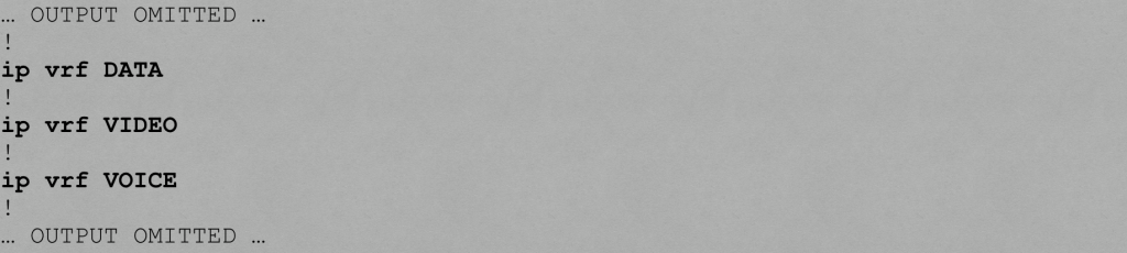
Step #1: Globally define one or more VRFs.
Below is the configuration on the COMMON router that defines our VRFs:
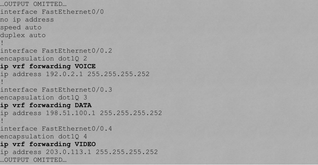
Step #2: Assign an interface or a subinterface to a VRF instance.
Below is the configuration on the COMMON router that assigns subinterfaces to VRF instances.
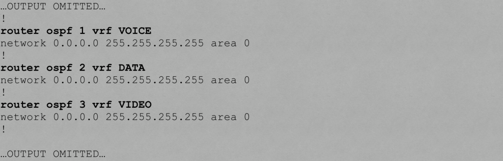
Step #3: Associate a routing process with each VRF.
Below is the configuration on the COMMON router that associates an OSPF routing process with each VRF.
Verifying VRF-Lite
You can use the show ip vrf command to display the VRFs you created on a router.

You can use the show ip route vrf vrf-name command to show a VRF’s IP routing table


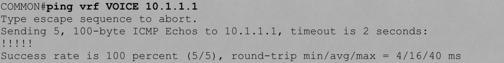
You can also use a VRF-specific ping to test connectivity with a remote IP address. For example, let’s say we’re on the COMMON router and wish to ping the Fa 0/1 interface on the VOICE router, which has an IP address of 10.1.1.1. How does the COMMON router know it needs reach that IP address over the VOICE VRF? Well, we specify the VRF name as part of the ping command.
I hope you enjoyed this discussion of VRF-Lite fundamentals, which is a topic covered in Cisco’s ROUTE curriculum. For more ROUTE training, check out my ROUTE Complete Video Course.
All the best in your studies!
![]()
Kevin Wallace, CCIEx2 (R/S and Collaboration) #7945, CCSI 20061

If you enjoyed this article, you might also want to subscribe to my podcast:
iTunes: http://kwtrain.com/podcast
