
Fundamentals of Border Gateway Protocol (BGP) - Part 3
Apr 08, 2019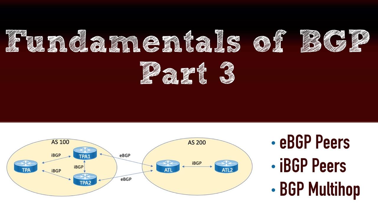
This post is the 3rd in a series of Border Gateway Protocol (BGP) posts. If you missed either of the first two, here are the links:
Now, in this post, you'll learn about how BGP neighborships are formed, within an autonomous system, between autonomous systems, and even between routers that are not directly connected. Also, we'll check out BGP authentication.
eBGP Peerings
Given that BGP is an AS-to-AS routing protocol, it would make good sense that external BGP (i.e. eBGP) is a key ingredient in its operations. The very first thing that we need to keep in mind with eBGP is that the standards are built so that there is a requirement for a direct connection. This is something that we can work around (of course), but this point is worth consideration. Because a direct connection is assumed, the BGP protocol does two things:
- It's going to check for a time-to-live (TTL) value, and that the time-to-live value is set to 1. This forces what appears to be a direct connection between EBGP peers.
- There is a check made to make sure the two devices live on the same subnet.
Another important point of consideration with eBGP peerings is the TCP ports that are going to be in use. This is especially important (and frequent) with firewall configurations that are protecting an autonomous systems. The first BGP speaker to initiate the state changes that are going to take place as the neighborship forms will source traffic from a randomized ephemeral TCP port, and the destination port will be TCP port 179. The responding BGP speaker will source traffic from TCP port 179, and the destination port will be the randomized ephemeral port. Firewalls must be adjusted to accommodate for the changes in communication based on which a BGP speaker initiates the session, and this could, of course, change for future a session. Some administrators will even put mechanisms in place to ensure the peerings formed are sourced from a known direction.
What about IPv6? Well, as stated earlier in a previous post, BGP is very flexible and welcoming of IPv6 since the protocol was originally engineered that way. You can form eBGP (and iBGP) peerings using IPv6 addressing even if you're carrying IPv4 prefixes for the network layer reachability information.
To form you eBGP peering, you do the following:
- Start the routing process for BGP, and specify the local AS (router bgp local_as_number).
- Provide the remote eBGP speaker's IP address and the remote AS number (neighbor ip-_of_neighbor remote-as remote_as_number).
Example 1 demonstrates the configuration and verification of an EBGP peering between the TPA1 and the ATL routers.

Example 1: Configuring an eBGP Peering

NOTE: To assist you when learning BGP, you might want to enable the debug ip bgp feature as you are building a peering. This will allow you to see the transition states in the neighborship. Also, to gain even more information about neighborships, you can use the command show ip bgp neighbors.
Creating an IPv6-based eBGP peering is also simple. The only real change is that we go under the address family for IPv4 and activate the neighborship. Address families in Cisco routers for BGP permit you to run many different Network Layer Reachability Information (NLRI) schemes under the same overall BGP process. Example 2 demonstrates the IPv6 peering approach.
Example 2: An EBGP Peering Configuration Using IPv6

iBGP Peerings
If you examine the topology closely, you might notice something that looks a bit strange. Why is there an iBGP peering created between TPA1 and TPA2? It looks completely unnecessary. Well, in this case, looks can certainly be deceiving. One of the main considerations you must master regarding BGP is the fact that there is something called the iBGP Split Horizon Rule. This rule states that no IBGP speaker can take in an update and then send that same update to another iBGP peer. Wow. This requires that we fully mesh our iBGP speakers in order to provide full awareness of prefixes.
Early on in the development of BGP, a full mesh of peerings was not a big concern. Especially if you are only talking about three routers like in our example. Unfortunately, over time, this requirement became untenable, and a couple of mechanisms exist (namely route reflectors and confederations) to work around this rule.
Another important consideration with IBGP is redundancy. We certainly want to establish multiple physical links between devices, but what happens if the link being used for BGP fails? How can we have an automatic cutover to a peering using an alternate link?
An easy way to solve this is to implement loopback addresses, and use these addresses to peer. This is something we will often do with our BGP peerings, and it might require, depending on your vendor, some additional commands in order to get it to work. For example, with Cisco, we must specifically indicate that the source of the peering is the loopback IP address.
NOTE: Another important consideration when peering between loopback addresses in iBGP is that the loopback addresses are actually reachable between the BGP speakers. This is where an Interior Gateway Protocol (IGP), such as OSPF or EIGRP, comes in very handy.
Example 3 shows the configuration of an iBGP peering between TPA and TPA1 devices. Note we use the loopback approach in the event we want to add redundant links between the devices in the future.
Example 3: Configuring an iBGP Peering

eBGP Multihop
During the eBGP peerings section of this post, we discussed the expectation by BGP that your neighbors be directly connected. During the iBGP section, we discussed the advantage of peering between loopbacks for redundancy. Now it is time to answer the question: What if your eBGP speakers are not directly connected? In fact, if we want to peer between loopbacks with eBGP to take advantage of potential redundancy, how would we do that, since the loopback interfaces are NOT directly connected with each other?
BGP solves this with the eBGP multihop option. With the eBGP multihop setting, you indicate the maximum number of permissible hops. This overrides the check by BGP for a TTL of 1 as we presented earlier in the post. But what about the requirement for a direct connection? BGP actually disables this check quietly in the background for us automatically when we use the eBGP multihop feature.
Example 4 demonstrates the eBGP multihop configuration between TPA1 and ATL. Multihop is needed here, because we are peering between the loopbacks of the devices.
Example 4: eBGP Multihop

BGP Authentication
Most organizations today add authentication to their BGP configurations in order to help protect them against a wide variety of attacks. Authentication helps to ensure that you do not just peer willing with any BGP speaker out there. Admittedly, this is a bit tougher to have happen to your BGP than with other routing protocols, since a configuration of peerings is a manual process that must be conducted on both of the devices wanting to peer. Even with this said, authenticating the devices (eBGP or even iBGP) is an excellent idea.
The great news is, Cisco makes it remarkably easy to add authentication to your peerings. You simply add a password (i.e. shared secret) on each device configured for the peering. Be sure to understand that this shared secret is going to appear in clear text (by default) inside of your configuration. You might want to consider using the service password-encryption command in order to do at least a weak encryption of those clear text passwords appearing in the router configuration.
Message Digest 5 (MD5) authentication is the result of your simple password configuration on the devices. Example 5 shows authentication added to the configurations for TPA1 and ATL.
Example 5: Configuring Authentication for your BGP Peers

That's going to wrap up Part #3 of our BGP series. Coming up in Part #4 we'll take a look at how we advertise Network Layer Reachability Information. Take good care.
